Popular Posts
-
 The MU to MU disallow feature allows the RF Switch to block communications exchanged between clients associated to a WLAN.With the Motorola ...
 -
 Pre-Requisites: Requirements: The following requirements must be met prior to attempting this configuration: One (or more) RF Switc...
 -
 RADIUS Authentication Attributes: The RADIUS protocol follows client-server architecture and uses the User Datagram Protocol (UDP) as de...
 -
 LDAP Server can be used as the database with WS5100 radius server. This document provides the details of configuration need to done for WS5...
 -
 WS5100 login: cli User Access Verification Username: restore Password: restoreDefaultPassword WARNING:This will wipe out the con...
 -
 IPSec VPN offers the security and encryption features necessary to protect enterprise data, voice, and video traffic as it traverses public...
 -
 Components Used: The information in this document is based on the following hardware and software versions: · 1 x RFS4000 Swit...
 -
 The following section outlines the configuration steps required to configure 802.11i with 802.1X and pre-shared keys on a RF Switch: 1) ...
 -
 Snipe-IT is a free and open source, cross-platform, feature-rich IT asset management system built using a PHP framework called Laravel ...
Hotspot Authentication - Configuration
Requirements:
The following requirements must be met prior to
attempting this configuration:
One (or more) RF Switches are installed and
operational on the network.
A Windows XP workstation is available with Microsoft
Internet Explorer or Mozilla Firefox to perform Web UI or CLI configuration.
The reader has read the Motorola RFS Series Wireless
LAN Switches - WiNG System Reference Guide.
Components Used:
The information in this document is based on the
following Motorola hardware and software versions:
1 x RFS6000 or RFS7000 Version 4.0.
4 x AP300
Access Ports.
Configuration:
The following section outlines the configuration
steps required to configure Hotspot Services on a
Motorola RF Switch:
1) Hotspot
Virtual IP Interface
2) Hotspot
Enabled Wireless LANs
3) Digital
Certificates and Trustpoints
4) Integrated
RADIUS Server
5) Integrated
DHCP Server
6) Web Based
Guest User Administration
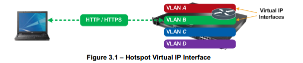
3.1 Hotspot
Virtual IP Interface:
Hotspot authentication requires direct IP
communications between the Hotspot user’s web browser and the Hotspot service
operating on the RF Switch. For Hotspot authentication to function correctly
the Hotspot user’s web browser session must be captured and re-directed to a
login page hosted on the RF Switch where the user’s credentials are forwarded
over a secured TLS channel. Additionally the Hotspot user’s web browser will be
further re-directed to a welcome or failed page depending on the outcome of the
authentication.
To facilitate the capture, re-direction and
authentication, a virtual IP interface must be created on the RF Switch and be
assigned to the VLAN servicing the Hotspot WLAN. If a virtual IP address is not
assigned to the Hotspot VLAN, the Hotspot feature cannot function.
To support Hotspot users it is recommended that a
dedicated VLAN and virtual IP interface be created so that the Hotspot users
are separated from the internal traffic. Additionally for public access
applications it is recommended that the secure management feature be enabled so
that management access into the RF Switch is only provided by the management
virtual IP interface.
The virtual IP address assigned to the Hotspot VLAN
must be sized accordingly to support the expected number of Hotspot users using
the Hotspot service. A good starting point would be to assign a /24 network
which can support up to 254 hosts, however there are no restrictions and larger
subnets can be implemented if required.
Creating a Virtual IP Interface using the Web-UI:
In the Switch Virtual Interface Configuration
window, specify a VLAN ID and Name. Specify an appropriate IP Address and
Subnet Mask then click OK. In this example Hotspot virtual IP address will be
set to 192.168.70.1/24 which resides on VLAN 70.
The virtual IP interface for the Hotspot service has
now been created.
The Hotspot VLAN can be assigned to an Access or
Trunk port which is connected to an Internet Router or Firewall. Alternatively
a public virtual IP address can be assigned to the RF Switch which can provide
NAT services between the Hotspot users and public Internet.
Hotspot
Enabled Wireless LANs:
The following example will demonstrate how to
configure an Internal Hotspot WLAN on an RF Switch. An internal Hotspot WLAN
will provide capture and redetection to basic Login, Failed and Welcome pages
hosted on the RF Switch.Internal Hotspot pages are hosted directly on the RF
Switch and support minimum customization. When enabled administrators can
modify only certain parts of the internal pages such as display text and company
logos. If advanced customization and page formatting is required, Advanced
Hotspot or External Hotspot should be utilized.
Creating
an Internal Hotspot WLAN using the Web-UI:
In the Web-UI select Network > Wireless LANs >
Configuration. In the Wireless LANs list highlight a WLAN you wish to use for
Hotspot authentication on then click Edit.
In the WLAN Edit window, enter a ESSID name and
Description for the Hotspot enabled WLAN. Specify the VLAN ID where a Virtual
IP Interface is assigned. The VLAN must have a virtual IP address assigned for
Hotspot capture, redirection and authentication to occur. Under Authenticationselect
Hotspot then click Config.
In the Hotspot window select the Hotspot type
Internal (default). Optionally:
1) Modify the
Title Text, Header Text and Footer Text for the internal Login, Welcome and
Failed pages.
2) Specify a
Small Logo URL and Main Logo URL. This will add logos to the Internal Hotspot pages.
3) Check the
option Use System Name in Hotspot URL. This will substitute the RF Switches Hotspot
virtual IP address with the switches hostname in the URL presented to the
Hotspot users web browser.
4) Specify
the number of Hotspot Simultaneous Users. This option will determine the
maximum number of simultaneous Hotspot users that can connect to the Hotspot
WLAN.
5) Enable
Logout On Browser Close. This option will de-authenticate the Hotspot user upon
closing their web browser.
Click OK.
If you select the option Use System Name in Hotspot
URL, the RF Switches hostname must be resovable by DNS for the capture and
redirection to function. If the hostname is not resolvable, the RF Switch will
not be able to present the login pag es to the Hotspot users.
In the WLAN Edit window click RADIUS. In the RADIUS
configuration window specify a Primary RADIUS Server Address. If using the
integrated RADIUS server on the RF Switch, the Primary RADIUS Server Address
should be set to the virtual IP address you assigned to the management VLAN.
Specify your RADIUS Shared Secret then click OK.
In the Wireless LANs list highlight the Hotspot WLAN
you just created then click Enable. If manual mapping of WLANs is disabled, the
Hotspot WLAN will be automatically mapped to all adopted radios on the RF
Switch. If manual mapping of WLANs is enabled, you will need to specify which
Radios support the Hotspot WLAN by clicking Network > Access Port Radios
> WLAN Assignment.
Apply and save the changes to the startup-config by
clicking Save.
Subscribe to:
Post Comments (Atom)
Social Icons


Popular Posts
-
 Overview WiNG version 4.0 includes a rich suite of features which are included with each RF Switch at no additional charge as well as...
 -
 RADIUS Authentication Attributes: The RADIUS protocol follows client-server architecture and uses the User Datagram Protocol (UDP) as de...
 -
 Snipe-IT is a free and open source, cross-platform, feature-rich IT asset management system built using a PHP framework called Laravel ...
 -
 Components Used: The information in this document is based on the following Motorola hardware and software versions: 1 x RFS6000 or ...
 -
 Capturing 802.11 frames with Ruckus Wireless access points and Wireshark Since many problems can be resolved only by closely inspecti...
 -
 WS5100 login: cli User Access Verification Username: restore Password: restoreDefaultPassword WARNING:This will wipe out the con...
 -
 Use of ARP Cache in a network device Most of the network devices will have anARP cache; the content of the same will be a collection of IP...
 -
 Components Used: The information in this document is based on the following hardware and software versions: · 1 x RFS4000 Swit...
 -
 The following section outlines the configuration steps required to configure 802.11i with 802.1X and pre-shared keys on a RF Switch: 1) ...
 -
 Requirements: The following requirements must be met prior to attempting this configuration: One RFS4000 or RFS6000 WLAN Switch Contr...
0 nhận xét:
Post a Comment